Whether you’ve designed a touch sensor before or this is a brand new adventure, it’s no surprise that a lot goes into the assembly to make the finished product function properly. Each layer plays a big role, but what are all of the layers that are needed?
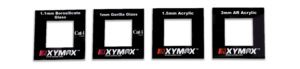
Top Lens or Cover Glass:
The top lens is the layer that users will touch, and is the most exposed to the environment. The end-use environment will help determine what material is best suited for the application.
- Polymer: Polymer materials are a cost-effective option, weighing less than glass and available in many standard thicknesses. Polymers are easy to screen print on to, add graphic decorations, and easier to cut and shape.
- Polycarbonate – very high impact resistance, can be hard coated to improve scratch and abrasion resistance (without a hard coat it is a relatively soft material that is susceptible to scratches), however, this material can start to yellow with UV exposure so it is not recommended for outdoor applications.
- Acrylic – scratch resistant, can be abrasion resistant coated to give improved properties, this material typically does not begin to turn yellow from UV exposure.
- Glass: Glass is extremely scratch resistant, and gives a nice user experience as it feels great to the touch.
- Chemically strengthened glass: processing increases strength 6-8 times that of non-strengthened glass
- Borosilicate glass: low coefficient of thermal expansion, and very stable
- Soda-Lime: the cheapest, standard glass
Sensor:
There are a lot of options when it comes to sensors:
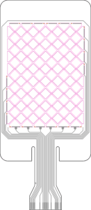
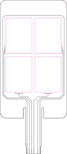
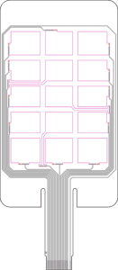
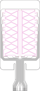
- Sensor Pattern
- Matrix: These are traditional touch screen sensors most familiar to people, they allow for touch points anywhere on the sensor. This sensor style supports gestures (swipe, pinch, zoom, etc.)
- Discrete: With discrete touch points, this sensor design has shown to better handle harsh user environment, prevent false touches, require less development time and be more cost effective.
- Slider: Allows users to slide along the screen for a variable selection, or to swipe between menus of icons. Combines the cost effectiveness of the discrete style sensor with the ability to touch at any point in the X direction and perform some degree of gestures including swipe.
- Sensor Material – there are many material options but the two most commonly used:
- ITO (Indium Tin Oxide): most touch sensors, especially stock sensors, are made with ITO. It is very brittle so it is unusable for curved applications.
- PEDOT: An extremely flexible polymer. PEDOT can be screen printed, however, it is slightly translucent so this method is not suitable for sensors with a display. Screen printed PEDOT is great for backlit areas that are touch sensitive (stationary icons is one example). For a crystal clear, transparent sensor, PEDOT can be processed onto Kodak HCF film.
- Sensor Size and Shape – the sensor size and shape should be decided after the display (if the application has a display) is chosen. While there are standard sensor sizes to choose from that are established based on consumer electronics, custom sensors can come in any shape or size to fit your requirements. Xymox has done round, square, some as small as 1 inch x 1 inch, and we’re working on one as large as 43 inches (on the diagonal).
- Sensor Tail Location and Length – The tail is the part of the sensor that connects to the electronics of the overall sensor assembly. The length of the tail can make a significant difference in the cost of the overall part, both through material costs and physical dimensions pertaining to manufacturing configuration. By positioning the tail in the optimal location, cost can be optimized and integration with the circuitry can happen in the best manner. Further, the assembly process can be streamlined to minimize labor and maximize throughput in your factory.
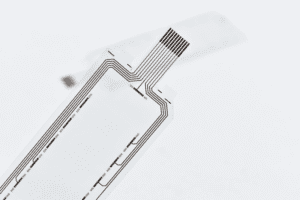
- Tail Type – There are two main ways to create the tail:
- Sensor Integrated Tail: An integrated tail is made by printing conductive traces on the same polyester sheet that the sensor is made from – it’s just an extension of the sensor itself. Integrated tails provide the most reliable connection to the sensor.
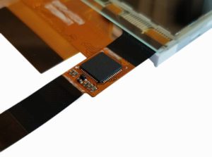
- Flexible Printed Circuit with Integrated Controller: This is when you use a tail made from a different flexible circuit and bond it to the sensor. This is the standard configuration for ITO sensors because ITO sensors are not flexible and would crack when the tail is bent to plug into the circuit board. One advantage of this style is the ability to include the controller for the sensor on the tail itself (called chip-on-flex or COF.) The disadvantage is that it is generally high cost.
With a custom solution, the sensor is typically laminated to the lens. This may seem insignificant, but to the touch controller and overall performance of the touch system, this difference is huge for two reasons:
- The sensor is closer to the user’s finger
- The sensor is moved further away from the display which reduces the amount of electrical noise seen by the display.
Display Insurance – Another benefit to laminating the sensor to the lens (rather than to the display) is that it helps with manufacturability and serviceability. All displays go end-of-life at some point. By removing the touch system from the display, the engineering effort can be significantly reduced saving time and money.
Controller:
A functional capacitive touch input system requires two things: a sensor and a controller. The sensor is one half, the touch controller is the other half of the touch input system. There are many types of controllers available, and you need the right pairing with the sensor to get it to work right.
PCB (Printed Circuit Board):
The PCB is the brains of the operation. Putting the touch controller on the PCB can offer significant cost savings as opposed to having the touch controller on an FPC (Flexible Printed Circuit).
 Bezel:
This is the casing that all of the components attach to. How the sensor and lens mount onto the bezel can have an impact on the appearance and ease of assembly and complexity of repair.
- Top mount looks clean and sleek but can be complicated for repair
- Bottom mount is often more assembly friendly and can offer ease of repair
Display or Backlighting:
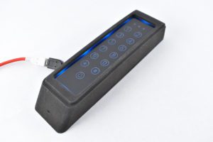
A traditional touch screen is used over a display (think: your phone), while a capacitive keypad will have static, touch sensitive icons enhanced with backlighting. A backlit touch keypad looks exceptionally slick if the icons are black until the LEDs illuminate it (this is called “deadfront”). The end use of the application will determine which is needed, display or backlighting; will this HMI (Human Machine Interface) require multiple menus of actions to perform? Then a display would be best suited.
There is a lot to consider when designing and developing a touch sensor. The good news is that you aren’t on your own. You can partner with experts like Xymox Technologies who establish the supplier relationships, buy the components and assemble the touch sensor. We deliver a turnkey solution that allows you to work with only one supplier. Let us help you make your job easier and contact us today!